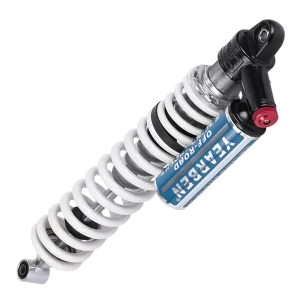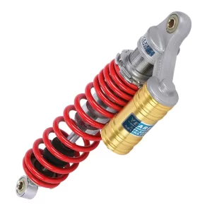
Truck seat suspension looks simple, a steel cylinder, some oil, a piston rod. But specifying the right hydraulic shock absorber for a fleet means getting three parameters right before you place an order: cylinder diameter relative to seat load, the damping force curve at the velocities your trucks actually see, and the seal system that determines whether the damper still works after three years of cab vibration. I’ve spent two decades in suspension engineering, and the pattern is consistent. Most seat damper failures trace back to a mismatch between the spec sheet and the real operating conditions. This article walks through each specification decision so you can write a sourcing requirement that holds up on the road, not just on paper.
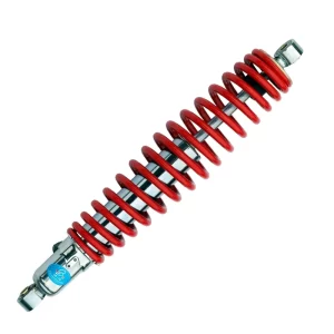
How a Hydraulic Seat Damper Controls Truck Cab Vibration
A truck seat hydraulic shock absorber is not a scaled-down chassis shock. It operates in a shorter stroke range, typically 40 to 80 millimeters, and its job is narrower: convert the kinetic energy of the seat-operator mass into heat through controlled fluid displacement, keeping vertical acceleration at the operator’s spine below the fatigue threshold over hours of highway or off-road driving.
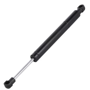
Inside the cylinder, a piston with calibrated orifices moves through hydraulic oil. When the seat compresses, the piston pushes oil from one chamber to another through these restricted passages. The resistance created, the damping force, is what prevents the seat from oscillating after every bump. Most truck seat dampers use a twin-tube design with a single-stage piston, though some heavy-duty applications move to monotube construction when sustained damping consistency is required across wide temperature ranges.
The key distinction from a chassis shock is the target frequency. Road inputs to the cab floor arrive at higher frequencies than what the chassis suspension handles, and the seat damper works on a much smaller mass. Getting the damping slope wrong here does not just degrade comfort. It introduces whole-body vibration into the operator at exactly the frequencies medical research links to long-term spinal injury. Our team specifies seat damper valving with this biomechanical window in mind, not just the mechanical fitment dimensions.
Cylinder Diameter and Stroke Length: Matching the Damper to Seat Load
Cylinder diameter is the first number that matters because it defines the damper’s working volume and, by extension, its ability to manage heat and resist fade under continuous cycling. For truck seat applications, we work with bores ranging from 24 millimeters up to 41.5 millimeters, and the choice is not arbitrary. It follows the seat’s designed load range.
| Cylinder Bore | Typical Stroke Range | Recommended Seat Load | Common Application |
|---|---|---|---|
| 24 mm | 40–60 mm | 50–90 kg operator | Light truck, delivery van |
| 28 mm | 50–70 mm | 80–120 kg operator | Highway tractor, bus driver seat |
| 35 mm | 60–80 mm | 110–150 kg operator | Heavy truck, construction vehicle |
| 38 mm | 60–80 mm | 130–180 kg operator | Mining truck, military vehicle |
| 41.5 mm | 70–90 mm | 160–220 kg operator | Heavy equipment, armoured vehicle |
A 24-millimeter bore in a seat carrying a 150-kilogram operator will overheat and lose damping force within the first hour of a shift. The oil volume is simply too small to shed the heat generated by the higher mass cycling through the stroke. Conversely, fitting a 41.5-millimeter damper to a light truck seat adds unnecessary weight, cost, and packaging complexity without any performance gain. The damper will feel overdamped and transmit more vibration than it absorbs because the valving cannot be turned down far enough to match the lighter load.
Stroke length must match the seat suspension’s mechanical travel. I’ve seen sourcing documents that specify the damper stroke longer than the seat mechanism allows, which means the damper bottoms out internally before the mechanical stop engages. Once that happens, the piston hits the foot valve repeatedly under load, and seal failure follows within months. Measure the actual seat travel at full compression and full extension before writing the stroke specification.
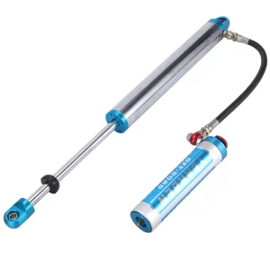
Damping Force Calibration for Different Truck Applications
Damping force is where most generic specifications fall apart. A damper rated at 800 newtons at 0.3 meters per second tells you almost nothing if you do not also know the force at 0.1 meters per second and 0.5 meters per second, the low-speed and mid-speed regions where seat dampers spend nearly all their operating life.
For on-highway trucks running primarily on paved roads, the damping curve needs a relatively steep compression slope with a softer rebound. This combination absorbs sharp pavement joints quickly and then allows the seat to return without launching the operator upward. For trucks operating on unpaved or deteriorated roads, mining haul trucks, logging vehicles, military transports, the requirement reverses. Rebound damping must be firmer to control the larger suspension inputs, and compression can be more progressive to avoid harshness on deep impacts.
Our seat damper valving goes through calibration on a dedicated dynamometer that maps force versus velocity from 0.05 to 0.6 meters per second, the full range a truck seat sees in service. The difference between a correct curve and an approximate one shows up as operator fatigue that accumulates over a shift. You cannot feel it on a five-minute test drive, but the operator feels it by hour six.
If your program involves mixed fleet conditions with some trucks on highway and others on gravel or site roads, it is worth confirming whether a single damper specification can cover both use cases or whether you need two valving profiles. I’ve found that a mid-range compression tune with adjustable rebound, calibrated at the factory, covers about 80 percent of mixed-duty fleets without requiring multiple part numbers, but that depends on the specific load range. Reach out at info@yearbenshocks.com with your fleet profile and we can run the numbers against our existing damping maps.
Seal System and Chrome Quality: What Determines Service Life
A hydraulic seat damper loses function in two ways: oil leakage past the rod seal, and internal bypass from wear on the piston band. Both failures start at the surface finish and the seal material selection.
The piston rod runs through a wiper seal, a primary pressure seal, and often a guide bushing at the cylinder head. Every time the seat cycles, the rod carries microscopic contamination, dust, cab cleaning chemicals, into the seal interface. If the rod surface finish is below Ra 0.2 micrometers or the chrome plating has porosity, that contamination embeds in the surface and turns the rod into a slow-cutting tool that shaves the seal lip with every stroke. We require a minimum of 20 micrometers of industrial hard chrome on every seat damper rod, with a surface finish of Ra 0.1 to 0.15 micrometers after polishing, and every rod goes through a salt spray test for 96 hours minimum.
The seal material choice depends on the operating temperature range. Standard nitrile seals work adequately in the minus 20 to plus 100 degrees Celsius range that covers most commercial truck cabs. For trucks operating in northern Canada or Siberian routes where cold-start temperatures drop to minus 40, we switch to low-temperature fluoroelastomer compounds that retain flexibility when nitrile has already stiffened. A stiff seal at cold start does not wipe the rod clean. It allows a thin oil film to escape on the first few strokes, and over hundreds of cold starts, that film accumulates into visible leakage and eventual damping loss.
Internal wear on the piston band is harder to detect because it does not produce external oil marks. The symptom is gradually decreasing damping force as oil bypasses the piston instead of flowing through the calibrated orifices. The only prevention is precision in the cylinder bore honing process. Our production line uses a three-stage honing cycle that hits a bore tolerance of plus zero, minus 0.02 millimeters with a crosshatch angle of 45 to 55 degrees, the window that balances oil retention for seal lubrication against bypass leakage. I’ve torn down dampers from suppliers who skip the fine-honing stage, and the bore surface under magnification looks like a plowed field after 500 hours of cycling.
OEM Sourcing: Spec Sheet, Sampling, and Production Lead Times
Writing a sourcing specification for a hydraulic seat damper requires more detail than most first-time buyers provide. The minimum data set we ask for from fleet operators and seat manufacturers includes the loaded seat mass range, the mechanical stroke limits of the seat suspension, the mounting eyelet dimensions and bushing durometer preference, the expected operating temperature range, and any corrosion resistance requirements beyond standard chrome.
Once we receive a complete spec sheet, the sampling process typically follows a three-stage path. Stage one is a dimensional and fitment sample, usually two to four units built to the agreed drawing, shipped within 15 to 20 working days for a standard configuration. The buyer checks bolt hole alignment, stroke clearance, and static fit before we proceed. Stage two is the production-representative sample, 10 to 20 units built on the production line with the final valving, seals, and chrome specification. These go through the full dynamometer test protocol and a 500,000-cycle durability run. Stage three is the pilot batch, typically 100 to 200 units, run at production speed with full process documentation, shipped for the buyer’s in-vehicle validation.
Production lead times depend on whether the damper uses a standard bore and stroke combination we already tool for, or requires new piston tooling and a unique valving calibration. Standard configurations ship within 25 to 30 working days from order confirmation. Custom-calibrated dampers with new valving typically run 35 to 45 working days for the first production batch, with that window shortening to the standard 25 to 30 days for repeat orders once the calibration is locked.
If your program has a firm SOP target, share your production timeline at info@yearbenshocks.com or call +86-523-86566899, and I’ll confirm whether a standard configuration can meet it or whether we need to adjust the sampling sequence to compress the qualification schedule. We’ve done accelerated sampling for programs where the fleet already has a validated seat platform and only needs damper qualification, and that cuts about two weeks from the standard timeline.
Common Questions About Truck Seat Hydraulic Shock Absorbers
What is the difference between a hydraulic seat damper and a gas-charged version?
A hydraulic damper uses only oil as the working fluid with an air or foam cell to accommodate rod displacement. A gas-charged damper pressurizes the reserve chamber with nitrogen, typically at 100 to 150 psi, which reduces oil aeration under rapid cycling. For truck seat applications, gas charging is most useful when the roads are rough enough that the damper sees high cycle rates over extended periods. For primarily highway trucks, a well-built hydraulic damper with an adequate oil volume performs identically and costs less. The gas charge itself is not what makes the ride better. It is what keeps the oil from foaming when the damper works hard, and most truck seats never push a damper into that regime.
Can I use the same seat damper across different truck models in a mixed fleet?
Across trucks from the same manufacturer with similar cab floor architecture, a single damper specification often works if the seat platform is consistent and the operator weight range overlaps. Across different manufacturers, or between highway tractors and off-road trucks, I recommend at least confirming the damping force curve on a dynamometer against the heaviest and lightiest seat configurations in the fleet. The mounting dimensions may be identical while the damping requirement differs by 30 percent or more once you account for cab floor vibration spectra. A five-minute dynamometer sweep costs far less than ordering 500 dampers that leave operators complaining about ride quality.
How long should a truck seat hydraulic damper last before replacement?
With correct specification and proper manufacturing quality, a seat damper should exceed 800,000 to 1,000,000 cycles, which translates to roughly three to five years in typical commercial truck operation. The fastest killers are bore corrosion from moisture ingress past a failed wiper seal, and over-stroking from incorrect mounting geometry that drives the piston into the end stops. If dampers in a fleet consistently fail within 12 to 18 months, the root cause is almost never the damper itself. It is either the spec not matching the seat load, the mounting geometry allowing side-loading on the rod, or a chrome plating process that was not validated for the actual operating environment. I’d want to see a failed unit cut open before ordering replacements. Share a photo of the failed damper and the seat model at info@yearbenshocks.com, and I can usually narrow the cause from the wear pattern alone.
If you’re interested, check out these related articles:
Lawn-Mower-Damper-Shock-Absorber
Steering-Damper-18MM
Hydraulic-Seat-Damper-Cylinder-Diameter-24MM
Lawn mower steering damper 18mm