The reliability of a hydraulic damper is decided on the factory floor, not on the drawing board. Decisions about chrome plating thickness, cylinder bore surface finish, and damping force calibration create the difference between a damper that delivers consistent performance for years and one that fades within months. After more than two decades overseeing shock absorber production and product development at Taizhou Yearben, I have seen how manufacturing discipline separates suppliers who deliver repeatable quality from those whose production spread undermines field performance. This article walks through each stage of hydraulic damper manufacturing, highlighting the engineering decisions that procurement teams rarely see but experience in every production batch they receive.
Material Selection and Component Preparation
A hydraulic damper begins with five core components: the cylinder body, piston rod, piston with valve stack, seals and guide bushing, and the hydraulic oil. Each must be specified and sourced to a tolerance that supports the final assembly, because variation in any single component multiplies through the damping curve.
Cylinder tubes are drawn from low-carbon seamless steel or aluminum alloy, selected based on the operating environment and weight target. For the majority of hydraulic dampers produced at Yearben, we specify cold-drawn seamless steel tube with a minimum yield strength of 235 MPa. The reason is straightforward: consistent wall thickness, held to ±0.05 mm, directly determines seal contact pressure around the full circumference. A tube with thickness variation creates uneven seal loading, which shortens seal life and produces a damping force that changes unpredictably as the piston rod strokes.
Piston rods carry the surface that matters most for leak prevention. The standard material is medium-carbon steel, induction-hardened to HRC 50-55 after machining, then ground and polished. For dampers exposed to moisture, chemical spray, or frequent washdown, such as those used on commercial lawn mowers and agricultural equipment, we move to stainless steel or specify additional surface treatment. The valve stack, assembled on the piston, consists of precision-stamped spring steel shims whose thickness, diameter, and stacking sequence define the force-velocity curve. Incoming inspection checks shim flatness to within 0.02 mm because a shim that does not seat flat against the piston alters the damping characteristic from the first cycle.
Precision Machining and Surface Treatment
If one manufacturing stage determines ultimate service life, it is surface treatment. Two processes matter above all others: chrome plating of the piston rod and honing of the cylinder bore.
The piston rod rubs past the seal and guide bushing on every stroke. Chrome plating thickness for hydraulic dampers typically falls between 20 and 30 microns. A layer thinner than 15 microns wears through within the warranty period; a layer thicker than 40 microns risks micro-cracking during deposition. At Yearben, we perform adhesion testing on every plating batch. A properly deposited chrome layer survives a bend test without flaking or peeling. I have analyzed field returns where chrome delamination destroyed the seal within 200 operating hours, a failure traced directly to insufficient pre-plating surface preparation in the supplier’s process.
Cylinder bore finish is the complement to rod surface quality. After honing, we target a surface roughness of Ra 0.2 to 0.4 μm. A bore finished below Ra 0.1 μm may look perfect but does not retain enough oil to lubricate the seal, while a bore above Ra 0.6 μm accelerates seal abrasion and produces stiction. Every cylinder we machine passes through a profilometer measurement before it moves to the assembly station.
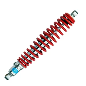
| Cylinder Diameter | Common Applications | Typical Wall Thickness | Surface Finish Target |
|---|---|---|---|
| 18 mm | Lawn mower steering dampers | 1.5 mm | Ra 0.2–0.4 μm |
| 24 mm | Seat dampers, light steering dampers | 2.0 mm | Ra 0.2–0.4 μm |
| 38 mm | Heavy equipment seat dampers, ride-on mower shocks | 2.5 mm | Ra 0.2–0.4 μm |
| 41.5 mm | High-load seat dampers, adjustable dampers | 3.0 mm | Ra 0.2–0.4 μm |
Assembly, Oil Filling, and Sealing
Assembly starts with the piston rod sub-assembly. The piston, valve stack, and retaining nut are torqued to a controlled specification, then the rod is inserted through the guide bushing and seal assembly. Alignment matters at this step because any eccentricity creates a side load on the seal lip that increases friction and accelerates wear.
Hydraulic oil selection depends on the application temperature range and duty cycle. For standard dampers operating between minus 20°C and plus 80°C, we use mineral-based hydraulic oil with a viscosity index of 100 to 150. Oil volume is metered to fill 85 to 90 percent of the internal cylinder volume, leaving a small gas pocket for thermal expansion. Under-filling causes damping fade as the oil heats and thins; over-filling produces hydraulic lock at full compression. In our assembly line, oil fill is automated and verified by weight to ±1 gram.
Seal installation is where process control becomes visible. The wiper seal, main oil seal, and O-ring must be installed in the correct orientation and order. A nicked seal lip might pass a brief leak test but fail after several hundred cycles. We use calibrated insertion tools rather than manual pressing for all critical seal installations, which keeps installation-related seal damage below 0.1 percent of produced units.
If your damper program involves varying load conditions or aggressive duty cycles, it is worth confirming your supplier’s chrome plating adhesion testing and bore finish inspection protocols before finalizing a production order. Reach out at info@yearbenshocks.com.
End-of-Line Testing and Calibration
Every hydraulic damper produced at Yearben undergoes end-of-line testing, not batch sampling. The test station applies a controlled sinusoidal motion and records both the force-displacement and force-velocity curves. We evaluate damping force at three piston speeds: 0.13 m/s, 0.39 m/s, and 0.52 m/s. For standard dampers, the acceptance window is ±10 percent of the nominal force specification. For premium and adjustable units, that tightens to ±5 percent.
Leak testing runs immediately afterward. The damper cycles through its full stroke while a pressure decay sensor monitors internal sealing integrity. A pressure drop greater than one percent over a 30-second hold triggers a failure and mandates rework.
For dampers destined for heavy-duty applications, such as those fitted to mining or construction equipment seats, we perform additional fatigue testing on a sample basis. A batch sample runs 500,000 cycles while we track damping force degradation. Force loss must remain under 15 percent over the test duration. This data feeds directly into our process control loop. If a batch shows higher-than-expected degradation, we trace the root cause to raw material, plating, or assembly before any units ship.
How Process Control Determines Long-Term Performance
When procurement teams compare hydraulic damper suppliers, the natural focus lands on unit price and quoted lead time. What is harder to evaluate, and far more expensive to overlook, is the manufacturing maturity that sits behind the quoted part. A damper that matches a drawing dimensionally but comes off an uncontrolled production line will generate field failures that no drawing review can anticipate.
At Taizhou Yearben, our manufacturing line produces over 1.5 million dampers annually across more than 200 models, serving global ATV brands and commercial lawn mower manufacturers. That throughput is not a marketing figure; it reflects the process consistency required to sustain high-volume OEM supply relationships. The same controls that deliver chamber-to-chamber consistency for a 24 mm seat damper also ensure that our 38 mm heavy equipment dampers perform to specification year after year.
Production consistency rests on three practical foundations. The first is raw material traceability. We log every batch of steel tube, chrome plating solution, and seal compound against the production orders it serves. When a field issue arises, we can trace it to the material lot, the plating bath, the assembly shift, and the test operator. Without that chain, root cause analysis becomes guesswork.
The second is in-process measurement. Waiting until end-of-line testing to discover a piston rod diameter out of tolerance means reworking or scrapping a fully assembled unit. At Yearben, critical dimensions are measured after machining and again after plating, and the data is trended. When a dimension begins drifting toward the specification limit, we adjust the tooling or process before it produces a nonconforming part. This is the difference between a supplier that controls quality and one that inspects for it.
The third is a factory culture that treats borderline results as warnings. A damper measuring 9.5 percent from nominal, technically within a ±10 percent limit, has met the specification but introduced variation that the customer will feel in application. The best manufacturing lines flag any result beyond ±5 percent for investigation, even when the formal acceptance window is wider.
If you are sourcing hydraulic dampers and want to understand how a supplier’s manufacturing process affects the product you will receive, send your part number and quantity to info@yearbenshocks.com or call +86-523-86566899. We can walk through the production steps that matter most for your specific application.
Common Questions on Hydraulic Damper Production
What is the difference between manufacturing a hydraulic damper and a gas shock absorber?
The fundamental distinction lies in the internal medium. A hydraulic damper uses only oil, while a gas shock adds a pressurized nitrogen charge behind a floating piston. In production, hydraulic dampers demand tighter oil fill tolerance because there is no gas charge to absorb minor volume variation. Gas shocks require an additional nitrogen charging station and a floating piston or bladder to the assembly line, adding sealing complexity. For applications where long-cycle damping consistency outweighs weight considerations, many manufacturers prefer hydraulic dampers because they eliminate gas pressure fade as a failure mode.
How do you prevent a hydraulic damper from leaking after months of use?
Leak prevention combines three factors: piston rod surface quality, seal material selection, and controlled assembly procedures. The rod surface is polished to Ra 0.1 to 0.2 μm after chrome plating, and any surface defect at this stage will cut a seal lip regardless of seal quality. We specify polyurethane seals with a Shore hardness matched to the operating temperature band and verify seal integrity through a full-stroke leak test on every unit before packing. A damper that passes these checks has a seal system designed to outlast its mechanical components.
What should a buyer look for during a hydraulic damper factory audit?
Beyond standard certifications and capacity figures, focus on three practical indicators. First, ask to review in-process inspection records, not only final test data. A factory that measures only at the end of the line is hiding upstream variation. Second, walk the plating area and ask about adhesion testing. A technically competent operation will describe the specific test method and pass criteria without hesitation. Third, observe how borderline units are handled. A factory that reworks dampers at the edge of the tolerance band, even when technically acceptable, is serious about delivering consistency to the customer.
What is the typical lead time for a custom hydraulic damper order?
Lead time splits into two scenarios. For a damper based on an existing cylinder family, with modified valving and mounting ends, four to six weeks is typical and includes prototype samples. For a fully new design requiring custom seal tooling or piston machining, plan for eight to twelve weeks from drawing approval to production samples. At Yearben, we provide a phased timeline after reviewing the drawing pack, breaking out tooling fabrication, first-article production, and testing separately so buyers can track progress against each milestone. If you are planning a new damper program, share your outline requirements with our engineering team and we will map out the timeline and any tooling considerations before you commit.
If you’re interested, check out these related articles:
Heavy Equipment Seat Shock Absorber 38mm
Damping-Adjustable-Shock-Absorber
Truck-Seat-Damper-38MM-Shock-Absorber-Manufacturer
Piggyback-2-0-Coilover-Shock
Triple-Bypass-Shock-For-Off-Road