A seat hydraulic damper that holds consistent damping force over thousands of hours begins with assembly precision that goes beyond bolting parts together. While the general sequence of fitting a piston, rod, and seal into a cylinder body is well understood, the specific torque on the body cap, the orientation of the rod seal lip, and the nitrogen fill pressure after welding are what actually determine whether the unit will still ride smoothly two years later. In over twenty years of engineering hydraulic dampers for trucks, construction equipment, and commercial seating, I have measured units where a single assembly deviation cut peak damping force by more than 15 percent and halved the expected seal life. This article explains the assembly stages that make the difference between a damper that performs predictably and one that fades early.
What Goes Into a Seat Hydraulic Damper
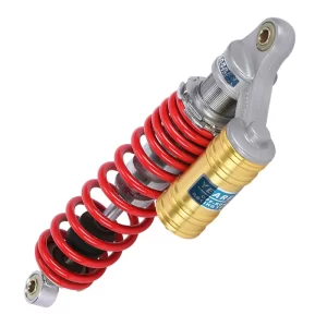
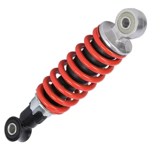
Every seat damper assembly starts with a steel cylinder body, a chrome-plated piston rod, a piston with a calibrated valve stack, a rod guide with a lip seal and wiper, and a rubberized mounting eye at each end. Most seat dampers used in commercial and off-highway vehicles are twin-tube designs with an inner working cylinder and an outer reservoir tube, although compact monotube units appear in some lightweight electric vehicle seats where packaging space is tight. The cylinder diameter typically ranges from 24 mm for compact operator seats up to 41.5 mm for heavy-duty mining and construction applications. Before any assembly step, each cylinder bore is honed to a consistent cross-hatch pattern to hold an oil film without allowing bypass, and every piston rod is checked for surface roughness under 0.1 µm Ra.
| Cylinder Diameter | Typical Seat Application | Damping Force Range |
|---|---|---|
| 24 mm | Light EV and lawn care seats | 300–600 N |
| 28 mm | Standard commercial truck seats | 500–900 N |
| 35 mm | Agricultural tractor seats | 800–1,400 N |
| 38 mm | Heavy truck and bus seats | 1,200–1,800 N |
| 41.5 mm | Mining and construction equipment seats | 1,600–2,500 N |
The Assembly Sequence for a Seat Hydraulic Damper
The assembly process follows a logical order that protects sealing surfaces and ensures the damping curve matches the design valve code. First, the piston valve pack is assembled on a clean bench with each shim oriented to the correct side of the piston. The piston is threaded onto the rod and torqued to specification, typically 18 to 25 N·m on a 10 mm rod. Next, the rod guide subassembly is prepped: the lip seal is inserted with its primary lip facing the pressure chamber so that oil pressure energizes the seal rather than blowing past it. The rod is then lowered into the inner cylinder filled with hydraulic oil; most seat dampers use a high-viscosity-index mineral oil in the 10W to 15W range to keep damping force stable across operating temperatures from minus 20°C to over 80°C. Once the rod guide is pressed into place and the cylinder cap torqued, the outer reservoir tube is slid over the inner cylinder and welded to the rod guide body.
The Mid-Step That Changes Everything
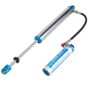
Between welding the reservoir tube and charging the damper comes a sequence of checks that many low-margin assembly lines skip, and that is where damping inconsistency enters the supply chain. Every welded joint is inspected under 0.6 MPa air pressure with the unit submerged to catch pinhole leaks, especially around the body cap thread area where off-axis welding can distort the seal seat. After the leak test, the damper is taken to its design stroke position and the nitrogen fill valve is opened; seat dampers are typically charged to 1.0–1.5 MPa of nitrogen through the reservoir to apply static pressure on the oil column and prevent cavitation during rapid compression. I have seen assemblies where the fill pressure was off by 0.3 MPa, and the resulting low-speed damping variance exceeded 20 percent on the force-velocity curve.
If your seat platform involves a steep static load distribution or frequent high-frequency inputs from washboard-style terrain, it is worth confirming that your supplier’s assembly line measures nitrogen fill pressure on every unit rather than batch-sampling only — reach out at info@yearbenshocks.com and we can walk through the assembly data that supports a given damping specification.
Precision Assembly Points That Directly Affect Damping Consistency
Three specific assembly operations control how tightly a production run holds its design damping curve. The first is piston-cylinder clearance. For a 35 mm cylinder, the diametral clearance between the piston OD and the honed cylinder ID should sit between 0.03 and 0.05 mm. A tighter fit raises seal drag and low-speed harshness; a looser fit allows excessive oil bypass that softens the damping curve and makes the unit feel undersized. The second is the valve stack preload. On a seat damper with a single-stage compression valve stack, the preload on the sealing shim is set by the piston nut torque and directly changes the knee speed where damping transitions from bleed-controlled to shim-deflection-controlled. A 1 N·m torque variation can shift that knee point by 0.05 m/s, enough to change the ride feel. The third is seal lip orientation. When the rod seal is reversed even one time during assembly, the lip won’t energize under pressure, and the damper will weep oil within the first hundred hours. We require assembly cell video verification on every rod guide build for custom OEM runs because optical inspection alone misses a reversed lip at full cycle speed.
Post-Assembly Testing Verifies Every Unit Before Shipment
After nitrogen charging, each seat damper goes onto a force-velocity test rig. The test protocol we run on every unit for seat dampers includes three cycles at 0.13 m/s, three at 0.30 m/s, and three at 0.52 m/s, at room temperature, with the damper mounted in its working orientation. The acceptance window is typically ±10 percent of the master reference curve for peak compression and rebound force at each speed. A unit that falls outside that window gets reworked or scrapped, because a damper that is 12 percent under on rebound force at 0.30 m/s will let the seat top out on bumps and bring a warranty claim. Seat dampers are not cycle-tested individually on the line unless it is a new qualification batch, but every new cylinder size and valve code goes through a 500,000-cycle durability test at full stroke before we lock the assembly procedure. The fatigue test especially reveals whether the snap ring groove machining or the rod guide crimp was weakened by a process change upstream.
Sourcing Seat Dampers When Assembly Quality Is Non-Negotiable
Procurement engineers evaluating hydraulic damper suppliers often focus on unit pricing and lead time first, but the more expensive metric is the assembly quality variation that creates in-field failures. Three questions I recommend asking during a factory audit are how the supplier controls piston nut torque (torque transducer with recording, not a click wrench), whether seal installation is verified by camera or operator checklist, and whether nitrogen fill pressure is measured per unit with a calibrated gauge and logged. Without those controls, even a well-engineered valve code produces inconsistent damping, and inconsistent damping in a seat damper causes operator fatigue complaints that are hard to diagnose because they are intermittent. At Yearben, every seat damper assembly cell uses recorded torque tools and in-line leak testing, and we supply the test data set with each shipment when the contract requires it. To discuss a damper assembly specification matched to your seat platform, send your part number and quantity to info@yearbenshocks.com or call +86-523-86566899.
Common Questions About Seat Hydraulic Damper Assembly
Which cylinder finish matters more for damping consistency?
The bore cross-hatch pattern inside the working cylinder has a greater effect on damping consistency than the rod surface finish alone. An inconsistent hone angle or a patchy finish causes oil film variation that shifts low-speed damping force unit to unit. I have traced 8 percent damping scatter back to cylinder bore roughness that drifted from 0.4 µm Ra to 0.9 µm Ra between honing tool changes.
Do seat dampers require a nitrogen charge if they are hydraulic only?
Yes, even a purely hydraulic seat damper benefits from nitrogen pressurization in the reservoir because it creates a static preload on the oil column. Without that preload, oil can cavitate behind the piston under sudden extension, producing a knock sound and a momentary loss of damping force. In programs we have supported, switching from a zero-pressure assembly to 1.2 MPa nitrogen eliminated customer-reported knocking entirely on cold-start conditions.
Is there a difference between thread-on and snap-ring body cap retention for seat dampers?
A threaded body cap provides a more uniform preload on the rod guide seal stack than a snap-ring retention, especially on larger cylinder diameters above 35 mm where housing flexure under bending loads can displace a snap ring. For heavy-duty seat dampers over 1,200 N damping force, we specify threaded caps to maintain seal alignment throughout the full stroke.
How can I verify that a supplier’s assembly process produces consistent damping before a trial order?
Request the supplier’s force-velocity test records for the previous three production lots of your target part number. Look for compression and rebound force standard deviation across a 30-unit sample at 0.30 m/s. A standard deviation under 5 percent of the mean indicates a stable assembly process with controlled torque and fill pressure, while anything above 8 percent usually points to hand-tightened pistons or unverified nitrogen charging. Share your requirements and we will confirm assembly and testing documentation availability before you schedule a first-article sample.
If you’re interested, check out these related articles:
Adjustable-Hydraulic-Shock-Absorbers
Gas Charged Dual Rate Coilover Shock Absorber