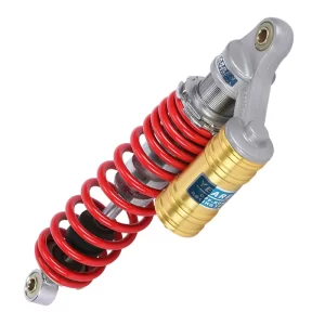
When an ATV, UTV, or off-road vehicle owner reaches for a damping adjustment knob, the expectation is that each click delivers exactly the change it’s supposed to. A click that feels vague or inconsistent isn’t just annoying, it means the suspension tune the rider relies on might be drifting and that usually traces back to how the clicker mechanism was machined, assembled, and tested. Adjustable shock clicker mechanisms achieve precise damping control because a small set of machined components must create a repeatable internal flow restriction for thousands of cycles, under pressure, without leaking or losing detent feedback.
What an Adjustable Shock Clicker Does Inside the Damper
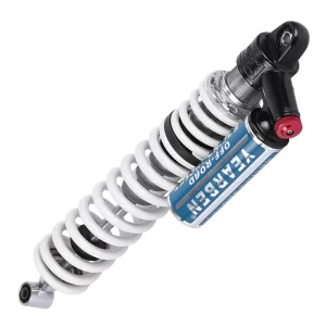
The clicker on a shock absorber is not a separate accessory, it is the external interface for a needle-and-seat metering valve that controls how much oil bypasses the main piston stack. At low shaft speeds, the piston’s valving generates relatively little resistance; a large portion of the damping force at those speeds comes from the bleed circuit the clicker regulates.
When the knob is turned, a threaded stem advances or retracts a tapered needle into a precision-machined port. Closing the needle forces more oil through the shim stack, increasing low-speed damping. Opening it allows more fluid to bypass, softening the initial response over small bumps. The number of distinct positions, the click count, is determined by a detent mechanism that indexes the knob rotation in fixed increments. The feel of those clicks, the “detent feedback”, is a function of a spring-loaded ball bearing engaging a series of grooves or holes in a rotating insert. Get the tolerances wrong and the clicks feel mushy or the needle position drifts under vibration. If the assembly leaks, air enters the damping circuit and the adjuster becomes useless.
Core Components That Determine Click Precision
Every adjustable shock clicker mechanism relies on a small set of interacting parts.
| Component | Typical Material | Key Role |
|---|---|---|
| Clicker Body | 6061-T6 aluminum, hard anodized | Houses internal parts, seals against shock reservoir cap |
| Adjuster Knob | 6061 aluminum or injection-molded plastic with overmold | Provides grip and visual index; couples to stem |
| Stem & Needle | Stainless steel or brass, ground finish | Meters oil flow through the bypass port |
| Detent Rotor | Hard anodized aluminum or steel ring with drilled dimples or formed grooves | Establishes click positions |
| Detent Ball & Spring | Chrome steel ball, stainless spring | Creates the tactile click feedback |
| Seals | Viton or NBR O-rings | Prevents external oil and contamination ingress |
The stack that makes the difference between a quality clicker and an unreliable one is the detent rotor and ball spring pairing. Spring force must be matched to ball diameter and groove geometry so that each click registers with a perceptible snap but without requiring excessive torque to turn. In our work with OEM customers, we’ve found that a detent force between 0.8 and 1.5 N·m per click is the sweet spot for gloved-hand adjustability while still holding position during off-road vibration. Below that range, riders report the knob shifting on rough terrain; above it, fatigue sets in after a few adjustments.
Precision Machining Steps from Aluminum Blank to Functional Body
The clicker body starts as a 6061-T6 aluminum round bar, usually 20 to 28 mm in diameter for most off-road and seat damper applications. The first operation is CNC turning to establish the outer profile, seal grooves, and internal bore that will accept the stem and needle assembly.
Bore concentricity relative to the sealing surfaces is the most critical dimension. A bore that is eccentric by more than 0.02 mm will cause uneven O-ring compression, creating a leak path that may not appear until the shock is pressurized to 300 psi or more and cycled through temperature changes. After turning, the part moves to a three-axis or five-axis machining center where detent holes, wrench flats, and any mounting features are cut. For clickers that index directly off the reservoir cap, the clocking of those features relative to the knob’s marked positions must be held to within ±0.5 degrees.
Once all machining is complete, the aluminum parts undergo hard anodizing, typically a Type III coating 25 to 50 microns thick. This layer hardens the surface to around 60 HRC, preventing galling between the aluminum detent rotor and the steel ball bearing over thousands of adjustment cycles. We have seen uncoated rotors wear their click grooves after as few as 500 cycles under test conditions, while properly anodized versions maintain consistent click force past 10,000 cycles.
Assembly Sequence and Detent Calibration
Assembly begins with a thorough cleaning of all components to remove machining debris and anodizing residue that could score seals or clog the needle valve. The stem and needle are installed into the body first, followed by the detent rotor and spring-loaded ball. A critical step during assembly is the application of a low-friction grease or assembly lubricant on the detent ball and groove interface, insufficient lubrication here leads to a gritty or inconsistent click feel from the first turn.
Once the internal stack is seated, the adjuster knob is pressed or threaded onto the stem and the assembly is sealed with Viton O-rings at each static and dynamic interface. The final step before testing is functional verification of the full click range. Every unit is turned to both endpoints to confirm the needle travels its full stroke without binding and that the detent engages cleanly in every marked position. If a click is missing or a double-click is felt, the assembly is rejected and stripped for root cause analysis.
In production batches, a sampling plan is also used to measure the actual flow area change per click using a flow bench. A good assembly shows a linear or progressive change in flow area, no click should produce a dead zone where the needle position changes but the flow coefficient stays flat because the needle tip geometry runs out of tolerance.
Testing a Clicker for Leakage, Torque, and Endurance
A clicker mechanism that leaves the factory untested is a liability. At minimum, every unit must pass a three-stage quality check.
Pressure integrity test. The assembled clicker is mounted on a test fixture that pressurizes the internal cavity to 150% of the shock’s maximum operating pressure, typically 450 to 600 psi depending on the damper design. The test holds pressure for 30 seconds while a mass flow leak detector monitors for any gas escape past the O-ring seals. A leak rate exceeding 0.5 sccm triggers a reject.
Click torque consistency test. A programmable torque tester rotates the adjuster knob through its full range at a constant speed while recording the peak torque required to move between each detent. The torque trace must stay within the 0.8 to 1.5 N·m window and no single click may vary by more than 20% from the adjacent click. A spike typically indicates a burr in a detent groove; a dip suggests a weak spring or shallow groove depth.
Cycle endurance test. A sample from each batch is mounted on a motorized cycling rig that runs the clicker through 5,000 full-range cycles at 2 Hz while the chamber is filled with hot shock oil at 80°C. After cycling, the click torque and pressure integrity tests are repeated. The unit must remain within 90% of its original torque values and show no measurable increase in leakage.
I have seen clickers pass the cold pressure test but fail after the hot cycle test because the O-ring material hardened or the anodized surface began to micropit under repeated ball contact. That distinction is why buyers evaluating a supplier should ask whether endurance testing is part of the standard quality release, not just a design validation activity.
Specifying Clicker Mechanisms for Your OEM Program
If you are sourcing adjustable shocks for an ATV, UTV, seat damper, or off-road vehicle project, the clicker mechanism should be the first component you inspect during a factory audit. Ask to see the machining tolerance control sheets for the detent rotor and body bore. A manufacturer that cannot document concentricity and groove depth variation is unlikely to produce clickers that feel identical across a batch of one hundred shocks. If your ordering scenario involves tight MOQs or specific click force requirements, our engineering team can review your target force window and confirm whether it is achievable with the chosen detent geometry. Send your part number and projected quantity to info@yearbenshocks.com for a technical assessment.
Common Questions About Adjustable Shock Clicker Quality
How many adjustment clicks are typical and what determines the count?
Most off-road and performance shocks offer between 10 and 30 clicks of adjustment, though the useful range often depends more on the needle taper and port geometry than the absolute count. The detent rotor’s groove count sets the maximum; a rotor with 20 equally spaced grooves yields 20 distinct positions. We’ve produced clickers with as few as 6 and as many as 36 clicks for specialized applications, but we generally recommend staying within the 12–24 click range because finer steps are difficult to feel through riding gloves and create unnecessary detent complexity.
Why do some clickers lose their crisp feel after a few months of use?
Almost always, the cause is wear between the detent ball and the aluminum rotor grooves, particularly if the rotor was not hard anodized or the lubricant washed out. A secondary cause is spring relaxation where the detent spring loses some preload from repeated compression cycles, especially in high-temperature environments. Replacing the spring with a higher-grade material and upgrading the rotor to hard anodized 6061 with a surface hardness above 55 HRC resolves this in most designs we have reworked for customers.
Does a clicker mechanism affect overall shock reliability?
It can. A poorly sealed clicker allows moisture and dirt to enter the damping circuit, which accelerates oil degradation and internal corrosion. The stem seal is the primary weak point; we specify a double-lip Viton O-ring with backup PTFE wiper for dirtier applications, and we test every unit at elevated pressure before shipment. If your vehicles operate in wet or dusty conditions, prioritize a clicker design with a proven leak-tight assembly and a documented IP rating for the external interface. Share your operating conditions with us at info@yearbenshocks.com, and we will confirm the appropriate seal specification for your program.
If you’re interested, check out these related articles:
Heavy Equipment Seat Shock Absorber 38mm
Triple-Bypass-Remote-Reservoir-Shock
Adjustable-Gas-Shock-Absorbers