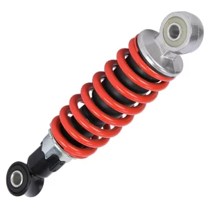
Long travel suspension engineering goes beyond simply adding longer shocks. It demands a system-wide approach that balances suspension geometry, damper valving, and manufacturing precision to survive real-world abuse. In our experience, many aftermarket kits claim extra travel but neglect the kinematic trade-offs that lead to binding, premature seal wear, and inconsistent damping. Over two decades of developing shocks for Baja buggies, desert racers, and high-output UTVs, we have learned that reliable long travel performance begins at the engineering drawing, not the parts catalog. The following sections unpack the critical design choices, production steps, and validation tests that separate a properly engineered system from one that will disappoint on the trail.
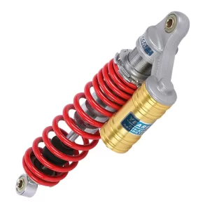
What Engineering Challenges Does Long Travel Suspension Solve?
Standard suspension is designed around a compromise between ride quality, packaging space, and cost. The result is limited wheel travel, which becomes a liability at speed over rough terrain. When a wheel runs out of droop or compression, the vehicle loses contact with the ground, forcing the driver to slow down or risk loss of control. Bottoming out also generates spike loads that damage chassis mounts and shock internals.
Long travel suspension addresses this by increasing the vertical arc the wheel can travel, keeping the tire on the ground longer, and reducing the frequency of severe bottoming events. The table below illustrates how travel requirements scale with vehicle platform and intended use.
| Vehicle Type | Typical Short Travel | Target Long Travel | Primary Use Case |
|---|---|---|---|
| UTV / Side-by-Side | 8–10 inches | 14–18 inches | Desert running, rough trails |
| Buggy (500–800cc) | 6–8 inches | 12–16 inches | Sand dunes, Baja-style runs |
| Trophy Truck | 10–12 inches | 24–30 inches | High-speed desert racing |
The engineering hurdle is that increasing travel forces a cascade of interdependent changes. Suspension links must be longer and stronger, shock mounts must relocate to accommodate new motion ratios, and the shock absorber itself must handle a longer stroke without fade or structural failure. Each of these variables affects the others. We have seen builds where a well-chosen damper was paired with poorly designed control arms, creating a bind condition that destroyed the shock body within a few hours of use.
Why Standard Suspension Fails at Speed
Standard suspension links are short, which exaggerates camber change and bump steer as the wheel moves through its arc. At low speeds this is tolerable. At 60 mph across rolling desert terrain, the same geometry causes sudden load reversals that overwhelm the damping circuit. The shock cannot dissipate energy fast enough, fluid overheats, and damping force fades. The driver feels the car float unpredictably. Our testing shows that a 40 percent increase in control arm length, combined with a properly positioned shock mount, can reduce peak linkage forces by roughly half while increasing usable travel. This mechanical rework must happen before any shock specification begins.
What Defines Adequate Travel for Off-Road
Adequate travel is not a single number. It depends on vehicle weight, spring rate, and terrain amplitude. A 1,500-pound buggy in Baja may need 16 inches of wheel travel to stay on top of massive whoops, while a 2,200-pound UTV in trail terrain might function well with 12 inches. The real metric is wheel frequency response—how quickly the wheel can accelerate to follow the terrain profile. Long travel combined with low internal friction in the shock gives the wheel assembly the physical freedom and speed it needs to stay planted. We verify this on shock dynos that map force vs. velocity across the full stroke length, checking for hysteresis that would indicate internal bind or poor lubrication.
How Are Long Travel Shocks Engineered for Maximum Articulation?
Once the suspension geometry is fixed, the damper itself becomes the dominant variable. A long travel shock must pack significant stroke into a package that still fits within the wheel well, withstand high lateral loads from angled suspension links, and maintain consistent damping force over thousands of heat cycles.
The starting point is body diameter and shaft size. A larger body—such as 2.0-inch or 2.5-inch tube—holds more oil, which improves heat dissipation and delays fade. For dune buggies and lighter UTVs, a 2.0-inch monotube body combined with a 5/8-inch hard chrome shaft often strikes the right balance between strength and weight. For heavier trucks and trophy applications, we move to 2.5-inch bodies and larger shafts to handle the energy input. The stroke is then set by the eye-to-eye length at full droop minus the compressed length, factoring in bump stop compression and chassis clearance.
How Bore Size Affects Stroke and Damping
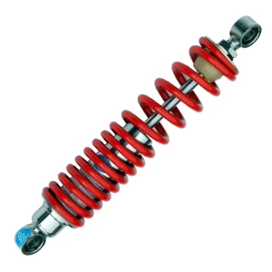
Bore diameter determines the piston area, which directly influences damping force capability. A 46mm piston in a 2.0-inch shock can generate roughly 30 percent less peak force than a 60mm piston in a 2.5-inch shock at the same fluid velocity, assuming identical shim stacks. This means the larger body shock can control a heavier vehicle without requiring extreme internal pressures that accelerate seal wear. In our OEM projects, we match piston size to vehicle corner weight and maximum expected shaft speed. Oversizing the body without the corresponding vehicle mass leads to an over-damped ride that skips across small chop. Undersizing creates a shock that overheats and fades on long runs.
Once bore size is set, the shim stack—a layered arrangement of steel discs on the piston face—provides the tunable damping curve. A common configuration for long travel desert use is a digressive stack on the compression side: high initial force to control body motion, then a blow-off point where the stiffness drops to absorb big hits without spiking the chassis. The rebound side typically uses a flatter curve to prevent packing. We have seen cases where a one-size stack from a catalog caused severe packing on successive whoops; the car lost travel after the third hit, bottoming out on the fourth. The solution required a custom shim arrangement that maintained recovery speed without sacrificing control. If your terrain demands a damping profile that falls outside the standard catalog offering, working directly with a manufacturer that can modify the stack is the only way to avoid these failures.
Why Reservoir Design Matters in Long Travel
Long stroke shocks displace significant fluid volume as the shaft enters the body. Without a reservoir, that displaced volume would compress the internal gas pocket to extreme pressures, causing cavitation and a drop in damping force at high shaft speeds. A remote reservoir, connected by a high-pressure hose, provides extra volume for the gas charge—typically nitrogen at 150–200 psi—and maintains consistent pressure across the stroke. Piggyback reservoirs, where the canister is clamped directly to the body, save space but offer less cooling than a fully remote unit. In sustained high-speed desert running, we recommend remote reservoirs with a separate hose for heat management. The hose assembly must be burst-tested to at least three times the maximum working pressure; we test ours to 4,500 psi as part of every production batch.
Which Manufacturing Details Determine Shock Longevity?
Engineering a good shock on paper is one step. Translating that design into a durable production unit requires manufacturing discipline that many low-cost suppliers skip. Long travel shocks operate in fine dust, mud, and water, under loads that can bend a shaft if not properly hardened and aligned. The difference between a shock that lasts one season and one that fails on the first outing lives in the factory details.
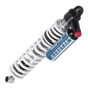
The inner bore finish of the shock body is the first non-negotiable. The piston ring and seal ride directly on that surface. If the finish is too rough, the seal wears rapidly and leaks. If it is too smooth, oil adhesion fails and galling occurs under high side loads. We specify a hard chrome cross-hatch finish with a surface roughness (Ra) of 0.2–0.4 microns, measured on every production batch with a profilometer. The chrome layer itself must be at least 20 microns thick to survive the life of the shock without flaking. When sourcing, ask for the Ra specification and plating thickness certification. A factory that cannot provide those numbers is not controlling this step, and the leak that follows will show up under warranty claims, not in the purchase order.
Shaft straightness and surface hardness are equally critical. A bent shaft, even a few thousandths of an inch out of true, creates a side load on the seal and piston, causing accelerated wear and friction. We centerless-grind shafts to a tolerance of 0.02mm on diameter and check straightness with a dial indicator before assembly. Hard chrome plating on the shaft runs to a Rockwell hardness of 70 HRC and is polished to a mirror finish, reducing stick-slip and preserving seal life. Shafts that skip the grinding step or use thin decorative chrome will show scoring within the first few hours of use, especially in sandy environments where grit embeds in the seal.
Seal choice is another failure point. Long travel shocks generate higher fluid pressures than short-stroke dampers, plus greater heat cycles that cause the seal lip to harden. We use a PTFE-backed seal with a secondary dust wiper in our off-road shocks, as the PTFE layer tolerates the heat and pressure while the dust wiper handles external contamination. For extreme conditions, a double-lip seal with an internal spring energizer provides additional redundancy. The cost difference between a basic nitrile seal and a PTFE-backed seal is small on a per-unit basis, but the reliability difference after 200 hours of desert use is dramatic. If you are ordering a bulk batch of shocks for a fleet, this single material choice will determine whether the warranty return rate is 1 percent or 15 percent.
How Are Long Travel Shocks Validated Before Shipping?
Design and manufacturing get the shock to the loading dock. Validation determines whether it behaves as engineered when a customer bolts it onto a vehicle. Validation is not a pass-fail glance. It requires instrumented tests that simulate the actual duty cycle a long travel shock will see.
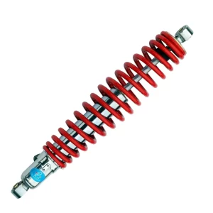
Every shock we produce passes through a dynamometer test that plots force vs. velocity at multiple stroke speeds, typically ranging from 0.1 to 1.0 meters per second. The dyno curve must fall within a pre-set tolerance band derived from the engineering target. A shock that is 10 percent off on compression at 0.5 m/s in the positive direction will behave differently from its mate on the same axle; the vehicle will pull or porpoise unpredictably. We run this dyno sweep at ambient temperature and again after a 30-minute heat soak cycle that brings the fluid to approximately 120 degrees Celsius to check for fade. Shocks that drift outside the band at high temperature are rejected and the root cause traced—usually a leaking piston seal or degraded shim stack alignment.
Beyond the single-shock dyno test, a sample from each production lot goes into a fatigue test rig that cycles the shock through its full stroke at 2 Hz for 150,000 cycles, roughly equivalent to a full season of desert racing, while continuously logging damping force and temperature. The shock is then disassembled and inspected for bore wear, seal damage, and shim stack deformation. This is not theoretical. In one case, a batch of shock bodies was found to have a slightly oval bore from a worn honing mandrel, causing a 20 percent increase in leak-down rate at 80,000 cycles. The mandrel was replaced and the batch scrapped before it reached a customer. Fatigue testing that runs less than 100,000 cycles, or testing that only runs at room temperature without heat cycling, does not replicate real failure modes and should be a red flag when evaluating a supplier.
Pressure decay testing of the gas chamber is another gate. Each shock is charged with nitrogen and left on a holding fixture for a minimum of four hours. If the pressure drops more than 2 percent, the shock is rejected and the assembly rechecked for seal integrity at the reservoir hose fittings and shaft seal. Gas pressure loss leads directly to cavitation and damping collapse, so this test is repeated as a spot check on outgoing shipments.
What Should Engineers Look for When Sourcing a Suspension Supplier?
Long travel suspension is not a commodity part. The supplier you choose either becomes part of your engineering solution or a recurring headache in your reliability data. Several criteria separate a factory that builds shocks for serious off-road use from one that merely stamps out copies.
First, in-house testing capability is the clearest signal of engineering depth. A supplier that owns a shock dyno, a fatigue test rig, and a profilometer for surface finish has invested in validating its output. A supplier that relies on an external lab for occasional testing is operating with a knowledge gap. When we audit potential partner factories, we ask to see recent dyno plots for a production shock pulled from inventory, not a pre-selected sample. If they cannot produce that within an hour, their process control is not where it needs to be.
Second, ask for the material certifications of critical components. The shock body tube should come with a mill certificate showing the alloy grade and wall thickness. The shaft should have a chrome plating certification specifying thickness and hardness. The nitrogen charge should be logged per shock with a timestamp. These documents prove that specifications are enforced, not aspirational. For projects requiring ISO compliance, our factory maintains full batch traceability from raw tube to finished shock, allowing a customer to audit a specific lot against its test records.
Third, understand the supplier’s ability to handle custom specifications. A catalog shock with fixed valving will only match a narrow window of vehicle weights and terrain. If your application falls outside that window—for example, a custom buggy with an unusually rear-heavy weight bias—a factory that can change the shim stack, spring rate, and reservoir hose length to your specs is the difference between a shock that works and one that must be reworked immediately. We regularly service OEM customers who provide us with their motion ratio and corner weight numbers, from which we calculate the required damping curve and spring preload. The iterative process may take two or three sample rounds, but the final production batch arrives ready to bolt on.
Finally, evaluate the communication structure. Large OEM projects involving multiple shock part numbers across different vehicle platforms require a dedicated engineering contact who can speak your language—literally and technically. A supplier that routes all technical questions through a sales rep who has never seen a dyno plot will create delays and costly translation errors. We assign a single program engineer to each OEM project, responsible for technical alignment from first sample through full production ramp.
Getting a Suspension System Engineered to Your Needs
Too many off-road builds start with expensive shocks and end with disappointment because the suspension was never treated as a system. The shock, the link geometry, the spring rate, and the vehicle mass distribution all interact. When any one of them is wrong, the result is a vehicle that bottoms out, fades, or handles unpredictably on the terrain it was built for. The fix is not a different shock brand. It is a properly engineered system from the start.
For OEMs, fleet operators, and custom builders who want a long travel suspension that is designed and validated as a complete package, send your vehicle specifications, target travel numbers, and intended terrain to info@yearbenshocks.com or call +86-523-86566899. We will review your requirements and propose a shock configuration—including body diameter, stroke, valving, reservoir type, and spring rate—matched to your operating conditions so the system works as a whole from the first lap.
Common Questions About Long Travel Shock Engineering
What is the difference between long travel and standard suspension?
A standard suspension is typically designed around 4–8 inches of wheel travel, prioritizing packaging, cost, and ride comfort for mixed road use. Long travel suspension extends wheel travel to 12 inches or more by using longer control arms, relocated shock mounts, and longer-stroke dampers. The effect is more articulation, better compliance over large terrain features, and reduced bottoming at speed. The trade-off is increased ride height, more complex steering geometry management, and higher loads on chassis mounting points, all of which must be addressed in the engineering phase, not as an afterthought.
Can any vehicle be converted to long travel suspension?
Conversion depends on the existing chassis architecture and intended use. Vehicles with independent front suspension can often accommodate extended control arms and longer coilover shocks if there is sufficient clearance for the larger articulation arc. Solid axle vehicles require a different approach, typically involving longer shock mounts and spring relocation. The chassis must be evaluated for stress at the new attachment points; reinforcement may be needed. For vehicles not originally designed for long travel, the cost and complexity of reworking the entire suspension system can exceed the value of the build unless the work is done as part of a full fabrication project.
How does shock length affect overall suspension performance?
Shock length sets the available stroke, but the suspension’s motion ratio—the relationship between wheel travel and shock travel—determines how much wheel movement results from a given shock stroke. A longer shock with the same stroke as a shorter shock may provide no additional wheel travel if the motion ratio is not adjusted. The correct approach is to determine the target wheel travel, calculate the required shock stroke based on the actual motion ratio dictated by the link geometry, then select a shock that meets that stroke while leaving enough compressed and extended length for the intended ride height and clearance. Simply buying a longer shock without recalculating the motion ratio can cause the vehicle to ride at the wrong height or limit droop in unexpected ways.
What maintenance do long travel shocks require to stay reliable?
Long travel shocks operate at higher fluid temperatures and see more abrasive contaminants than street dampers, so maintenance cycles are shorter. We recommend inspecting the shaft for scoring and cleaning the dust wiper after every outing in sandy or muddy conditions. A nitrogen pressure check should be performed every 30–40 hours of use, as even a small pressure drop degrades high-velocity damping. Full oil service, seal replacement, and shim stack inspection are typically due after 100–150 hours of hard off-road use, though the interval depends on terrain and vehicle weight. Skipping this service invites cavitation, bore scoring, and eventual shock failure. If you need guidance on a maintenance schedule matched to your specific vehicle weight and terrain, share your usage data and we will recommend a plan that keeps damping consistent through a full season.
If you’re interested, check out these related articles:
Hydraulic-Seat-Damper-Cylinder-Diameter-24MM
Off-Road-Coil-Over-Shocks-Manufacturer