Custom bypass shocks fail when a buyer locks in travel and spring rate but leaves zone placement, tube count, and valving assumptions unstated. That is the most expensive way to order. A bypass shock is not a single calibration; it is a position-sensitive damper whose behavior changes as the shaft moves through specific zones. We treat those three decisions as the core of the order because they determine whether the shock works with the vehicle or against it. Specifying them early catches the errors that no amount of clicker tuning can correct later.
Zone Tuning and Compression Placement
Zone tuning starts with shaft position, not spring rate. A bypass shock adds external tubes that open a passage around the piston at predetermined points in the stroke. The compression zone closest to full bump usually carries the highest valving load because it controls bottoming energy. The zone just above it manages mid-corner or whoop-section support. The rebound zones on the opposite side of travel shape how the wheel returns after impact.
We ask for four measurements before assigning zone locations: extended length, compressed length, wheel travel, and motion ratio. Without motion ratio, a zone placed 25 mm from full bump may feel completely different on a trailing arm than on a direct-mounted axle. That single detail causes more rework than any other part of a custom bypass shock order. On vehicles with high link ratios, we move the high-energy compression zone farther from full bump so the bypass opens before the piston reaches the wall of fluid. On a ratio close to one-to-one, the same zone can sit closer to the end of the shaft.
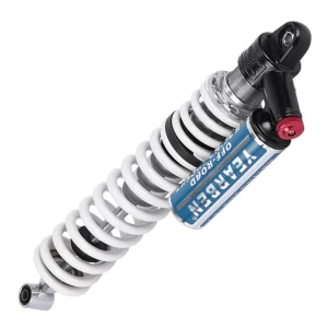
Zone placement also changes how heat builds in the shock. When a zone opens late, oil moves through the piston stack longer and generates more local temperature rise over repeated cycles. Opening the bypass earlier shifts some of that work to the external circuit and gives the main piston a shorter heat soak. That is why we want to know the race or duty cycle before finalizing tube location. A shock meant for short desert sprints tolerates a different zone map than one running continuous whoops for forty minutes.
The practical rule we use is simple: fix the two full-bump compression zones first, then place the rebound zone after the vehicle owner describes what the rear or front axle does on landing. If the axle kicks upward after a G-out, the rebound bypass usually needs to open later, not earlier. If the wheel packs down over repeated bumps, the compression zone is likely staying closed too long and the stack is resisting the next input.
Tube Selection for Custom Bypass Shocks
Tube count is the first part of the custom bypass shock order that separates a tuner from a catalog buyer. More tubes do not mean more control; they mean more zones of external adjustment. A two-tube shock handles low-speed compression and high-speed compression as two coarse steps. A three-tube shock adds a rebound or split compression stage to isolate the middle of the stroke. Four-tube and larger shocks go further, but they add plumbing, hose mass, and setup time that a UTV or mid-size buggy rarely needs.
The table below shows how we map tube count to vehicle use. The values are starting points we use in factory conversations, not fixed rules.
| Tube count | Stroke coverage | Common vehicle | Tuning tradeoff |
|---|---|---|---|
| 2 tube | Two compression zones, single rebound | Short-course buggy, lightweight UTV | Simple to dial in, limited mid-stroke separation |
| 3 tube | Two compression zones plus rebound split | Trophy truck, 4×4 desert racer | Strong packaging balance, more hose routing |
| 4 tube | Three compression zones plus rebound | High-power prerunner, heavy rear axle | Fine grain control, longer setup time |
| 5 tube | Four compression zones plus rebound | Unlimited class, custom chassis | Maximum zone resolution, requires data to use |
We tend to specify two-tube or three-tube bypass shocks for most custom orders because the added adjustments on larger tube counts only matter once the chassis data exists. If the team cannot yet identify where the axle speed spikes, adding a fourth zone simply spreads uncertainty across more adjustment points. Start with fewer tubes and reserve the remaining space for a remote reservoir or a larger body. That leaves the package simpler and reduces the chance of a hose being crushed under full articulation.
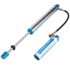
When customers ask us to copy a tube layout they saw on a race truck, we ask two questions. What is the motion ratio, and how much shaft travel is actually used? A tube position that works at 450 mm of travel does not scale down to a 280 mm UTV shock without moving the zone threshold. Scaling zones is not linear because oil displacement across the piston changes with shaft speed, not just stroke position. This is where most catalog specs lose their value.
Valving Stack Configuration for Custom Bypass Orders
Valving is where the order becomes specific to the corner weight and motion ratio. The shim stack controls how the shock resists shaft movement before the bypass tubes open. In our custom bypass shock builds we define the stack in three layers: low-speed shims that respond to small shaft movements, mid-speed shims that carry the transition, and high-speed shims that control sharp square-edge impacts. The clicker then adjusts low-speed bleed on top of that stack. It does not replace the stack.
A common mistake is selecting clickers first and treating the base valve as an afterthought. Clickers only alter the bleed path; they cannot change the pressure threshold where a bypass tube opens. If the base stack is too stiff, the shock will feel harsh below the zone threshold and the clicker will be used to mask it. We build the stack around the vehicle’s sprung mass and then use clickers for fine trim between different terrain types.
Oil viscosity and nitrogen pressure interact with the stack more than most buyers expect. In one of our desert programs, we kept the same shim layout and raised nitrogen pressure to control cavitation after a long high-speed run. The cavitation disappeared, but the compression curve also shifted earlier in the stroke. The correct fix was a slightly smaller clamp shim, not more pressure. That kind of interaction is why we ask for vehicle weight, spring rate, and expected shaft speed before cutting the first order.
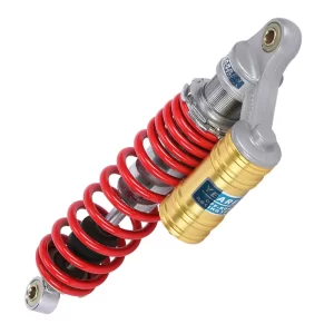
On adjustable models, the clicker range should stay close to the center of the adjuster. If the customer needs to run the clicker at full stiff or full soft to make the shock work, the base valving is wrong. We prefer to hand the driver a shock that starts near the middle of the range so there is room to soften for sand and firm up for hardpack without revalving.
Every custom order gets a written valving record with shim diameter, thickness, count, and stack order. This record matters later when the customer wants a revalve or a matched second set. Without it, even the same model shock can drift from batch to batch because small shim substitutions change the knee point without changing the part number.
Factory Bench Testing and Production Checks
Before any custom bypass shock leaves the factory, it passes two stations. The first is a dyno sweep across the full shaft travel, which records force at multiple shaft speeds and confirms the zone transitions open where the spec says they should. The second is a nitrogen leak and seal check under pressure. A bypass shock can look finished on the outside and still lose charge through a poorly seated hose fitting after a few heat cycles.
We then cycle the shock through its travel with the intended hose routing. A common failure occurs when the hose clears the shock body at ride height but contacts the spring retainer or frame rail at full droop. We mark attachment angles and clock the fittings before welding brackets. This saves the customer from discovering the problem after the truck is assembled.
Production checks also compare each shim stack to the valving record. A missing thin shim can change mid-speed force by enough to make the truck wander across whoops. Our factory assembles custom bypass shocks with the same traceability used on OEM damping parts: each shock receives a build sheet tied to the order number, valve setting, charge pressure, and dyno file.
If your program involves a mixed fleet where front and rear shocks will be revalved over two seasons, it is worth confirming zone maps and stack records before finalizing the bill of materials. Send your corner weights and motion ratio to info@yearbenshocks.com and we will check whether the current tube and valving proposal covers the full duty cycle.
Inquiry Preparation and Order Confirmation
Most custom bypass shock inquiries stall because the buyer sends only a photo and a travel number. We can work from that, but the order becomes faster and more accurate when the specification covers a few basic values. The three that matter most are extended and compressed length, corner weight with the intended spring, and motion ratio or wheel travel. Zone position and tube count follow from those numbers.
If you are not certain of the motion ratio, send the suspension type and the mounting points. We can calculate the ratio and propose a starting zone map. That removes the guesswork from the first quotation and gives you a valving target that matches the vehicle instead of a catalog axle weight.
To start a custom bypass shock order, send your vehicle type, shock length, spring rate, corner weight, and the terrain you need to survive to info@yearbenshocks.com or call +86-523-86566899. We will return a written zone map, tube count, and valving recommendation before you commit to production.
Common Questions About Custom Bypass Shocks
Can I copy a valving spec from another truck and expect the same ride?
No. A valving spec transfers only when the motion ratio, corner weight, and shock length are nearly identical. The shim stack that controls an 1,800 kg axle works differently on a 900 kg UTV because shaft speed at the same wheel movement is not the same. Spring rate also changes how far the shaft moves before the bypass zone opens. If the donor truck uses a trailing arm and your vehicle uses a solid axle, the zone thresholds need to move. Copy the starting idea, not the numbers.
What if I do not know my zone positions yet?
Most buyers think they need a fully developed zone map before requesting a quote. They do not. A useful starting map comes from shock length, wheel travel, motion ratio, and the terrain the vehicle sees most often. We use those values to place the full-bump compression zones first and then set the rebound threshold. The first map is a test target, not a final answer. It gives the factory something to build and the driver something to evaluate.
How many bypass tubes should I start with?
It depends on whether the shock is for a link-driven race truck or a trail UTV. A lightweight UTV rarely needs more than two compression zones because shaft speed stays low and the travel is short. A high-power desert truck with long travel and a heavy rear axle usually starts with three tubes so the middle of the stroke can be separated from full compression. We recommend starting with fewer tubes than you think you need. Extra zones only become useful after the first dyno file shows where the shaft speed actually spikes.
Does tube position affect oil temperature as much as valving does?
In the desert and dune programs we have run, tube position changes heat soak more than most valving changes do. When a zone opens late, the piston stack does the work for a longer portion of the stroke and oil temperature rises faster over repeated cycles. Moving that zone earlier shifts energy to the external circuit and gives the main piston a shorter heat soak. If your current shock runs hot or fades, share your travel data and duty cycle with us and we will confirm the zone and valving direction before you commit.
If you’re interested, check out these related articles:
Fixed-Preload-Atv-Shock-Absorbers
Driver-Seat-Damper-24MM-Cylinder-Diameter