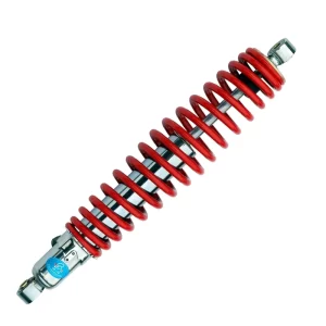
Every UTV shock absorber I’ve signed off for production over the past two decades has passed through a sequence of checks that most buyers never see. The logic behind that sequence matters. UTV shock absorber testing is not a single pass/fail gate — it is a layered validation that starts with the design envelope and ends with a set of data points the factory uses to decide if a batch ships. The process answers one question repeatedly: will this shock perform to spec for the life the customer expects? Most overviews stop at a list of test names. What they miss is the engineering reasoning that turns test data into a quality decision. That is what I want to walk through here from the manufacturer’s side.
What Testing Do UTV Shock Absorbers Go Through Before Shipping
A pre-shipment test protocol for UTV shocks can be broken into three waves. First, every shock absorber undergoes a pressure hold and visual inspection. Second, a sample from each production lot moves to the shock dyno for force-velocity mapping and gas pressure verification. Third, selected units enter environmental cycling and endurance runs that compress months of trail use into days. The specific tests depend on the shock type — a piggyback reservoir coilover faces different stress paths than a remote reservoir bypass shock — but the sequence always follows the same principle: prove that the assembly holds pressure, confirm that damping matches the design blueprint, and then challenge the unit beyond its rated duty to identify the earliest failure mode.
What Gets Checked Before the Shock Ever Hits the Dyno
Every unit built at our facility moves through a final assembly checklist. The shaft is inspected for chrome finish defects under magnification. The seal head and floating piston position are verified against the build sheet. Threaded preload collars on coilover shocks are checked for torque within the specified range. We pressure-test the nitrogen chamber and hold each shock for a minimum of 30 seconds while watching the gauge — any needle movement triggers a reject. This early gate catches assembly errors before they turn into dyno anomalies later in the day.
How Dynamic Performance Is Measured on the Shock Dyno
A shock dyno is not a marketing exercise. It is the tool that turns subjective ride feel into repeatable numbers. Each production lot sample is mounted on a Roehrig or equivalent hydraulic dynamometer and cycled through a matrix of shaft speeds — typically from 0.05 m/s to 0.5 m/s or higher depending on the shock’s intended velocity range. The dyno plots force against velocity for both compression and rebound strokes. What we are looking for is not just a smooth curve but one that sits within a defined tolerance band around the target damping profile. If the mid-speed rebound knee falls outside the window on three consecutive samples, the line stops and valving is rechecked.
One thing I’ve learned from years of matching shocks to vehicle specifications: the dyno alone cannot predict how a shock feels on a UTV. It validates the mechanical signature. The gap between dyno approval and real-world performance is closed by correlating force-velocity data with known vehicle dynamics. For example, a common setup for a 1,000-class side-by-side requires a rebound-to-compression ratio that keeps the chassis settled after a whoop section without packing up. You can see that ratio on a dyno graph if you know which velocity zone to read. Most test reports just print the peak forces. The value comes from interpreting the shape.
| Test Parameter | What It Verifies | Common Acceptance Window |
|---|---|---|
| Compression force at 0.3 m/s | Damping control during mid-speed impacts | ±10% of target value |
| Rebound force at 0.1 m/s | Low-speed chassis stability | ±12% of target value |
| Peak rebound force at 0.5 m/s | High-speed recovery from full compression | ±10% of target value |
| Hysteresis area | Internal friction and seal drag | Less than 15% of total force area |
| Gas pressure after cycling | Nitrogen charge integrity | Static pressure ±3% of spec |
Pressure, Leak, and Fatigue Tests That Predict Service Life
After the dyno run, the same test samples go through a durability loop that simulates the abuse a UTV shock sees over hundreds of hours. A cyclic load test applies a programmed displacement waveform at a fixed frequency — often 2 Hz to 5 Hz — for 50,000 to 100,000 cycles while logging damping force, rod temperature, and gas pressure at intervals. If the seal head temperature climbs beyond 120 °C on a non-reservoir shock without a corresponding fade in the dyno baseline, we know the friction stack is generating heat that will shorten seal life once the unit is in the field.
One failure mode that only shows up under cumulative heat load is cavitation in the oil. When the shock cycles hard enough to pull the pressure in the compression chamber below the vapor point of the fluid, bubbles form and collapse. That collapse erodes the piston shim edges and produces a damping curve that drifts open over time. Our fatigue program includes a cavitation detection step on every new valving configuration: we run the shock at increasing stroke amplitudes until we see the force curve develop a sudden discontinuity on the compression side. That amplitude becomes a hard limit in the customer’s installation instructions.
Reservoir and Hose Integrity Under Pressure
Remote reservoir shocks add another failure path: the high-pressure hose and its fittings. Each remote reservoir assembly is proof-tested at 1.5 times its working pressure before being paired with the shock body. We cycle the hose through a bend fixture that replicates steering lock-to-lock articulation while the system is at full charge. Any pressure drop of more than 0.5 bar during the bend cycle cycle is considered a leak. This is one area where skipping test steps shows up quickly in the field as a shock that loses damping halfway through a ride.
How Factory Test Data Predicts Real-World UTV Performance
The jump from a clean dyno sheet to a desert race course is not automatic. We close that gap by anchoring every test limit to a specific vehicle event. For instance, the high-speed compression force window on a coilover shock for a sand rail is set tighter than for a trail UTV because the sand rail spends more time at full bump velocity. I’ve seen cases where a shock that dynos perfectly within a ±10% tolerance band still bottoms harshly on the vehicle because the bump stop engagement point was calibrated for a lighter spring rate. That mismatch shows up in the velocity region above 0.5 m/s on the dyno, but only if you overlay the spring rate curve and corner weight calculation on the same plot.
When a buyer asks me whether a shock is “good,” I usually ask what vehicle, what terrain, and at what pace. The test data can only answer those three questions if the factory has built a database of vehicle-specific correlations. Without that database, the numbers on the report are just numbers. This is the practical difference between a supplier that tests to a generic standard and one that tests to a vehicle-specific spec. The second approach costs more in engineering time up front, but it eliminates the re-valving loops that eat into a distributor’s margin afterward.
If your program requires a shock that must hold consistent damping after repeated high-speed runs, ask for a correlation report that maps dyno force-velocity data to actual vehicle accelerometer logs. We compile those for every new platform we develop. Most generic test reports do not include that linkage. When you are sourcing at volume, the presence or absence of that report often predicts how much field tuning you will have to absorb later. If you want to see how we structure that data for a specific UTV platform, send your model and usage profile to info@yearbenshocks.com and I’ll walk you through a sample correlation.
What High-Quality Testing Means for Your Sourcing Decision
Pre-shipment testing is not just an internal quality gate. It is the only reliable predictor of field failure rate, warranty cost, and brand reputation for any company integrating UTV shocks into a vehicle or selling them as aftermarket parts. A factory that tests every lot on a dyno and maintains a fatigue database has fewer hidden variables downstream. The testing data also becomes the baseline for any future cost-down exercise: if you cannot reproduce the same damping signature on a lower-cost valving stack, the dyno makes that visible before the first container leaves the port.
Our approach at Yearben gives me a clear recommendation for sourcing teams: ask for a dyno sheet from the specific production batch your order will ship from, not a golden sample from six months ago. The difference between the two often tells you more about the supplier’s process control than any audit checklist ever will. When you see batch-level test data, you are looking directly at how the factory manages variation in piston machining, shim thickness, and oil viscosity — the exact variables that cause ride quality complaints after installation.
Common Questions About UTV Shock Absorber Testing
Is a shock dyno test the same as a vehicle test?
No. A dyno measures the shock as an isolated component under controlled motion inputs. A vehicle test records chassis acceleration, driver feedback, and component temperatures under real terrain loads. Both are needed: the dyno confirms mechanical consistency batch over batch, while the vehicle test validates that the damping profile matches the intended ride character. A shock that passes the dyno can still feel harsh on the vehicle if the spring rate and motion ratio were not accounted for in the damping target.
How many cycles should a UTV shock survive in a fatigue test?
It depends on the duty cycle. For a trail-oriented UTV that sees moderate speeds, a 50,000-cycle program at 2 Hz with a stroke equal to 80% of travel is sufficient to identify seal and bushing degradation. For desert racing applications where shocks see sustained high-speed operation, we extend the program to 100,000 cycles and include a mid-test oil analysis that checks for viscosity loss. In our experience, a shock that survives 100,000 cycles without a 10% drop in damping force will deliver reliable service on a race truck for an entire season.
Why do some UTV shock absorbers lose nitrogen pressure sooner than others?
Nitrogen loss almost always traces back to one of three causes: a micro-leak at the Schrader valve that was not detected during the hold test, permeation through the bladder in a reservoir shock that was stored without regular cycling, or installation damage where the reservoir hose was twisted during mounting and cracked the inner liner. In well-built units, pressure loss should be less than 2% over a storage period of six months when the shock is kept at ambient temperature and cycled once before measurement.
Can a factory adjust valving based on test feedback for a custom order?
Yes, and this is where batch-level testing adds the most value. When we receive a customer’s vehicle weight, motion ratio, and intended use, we select a baseline valving stack and build a small pre-production batch. That batch goes through the full dyno and fatigue protocol. If the dyno curve shifts outside the target after fatigue, we adjust the shim stack configuration — often by adding or removing a single shim in the rebound stack — and retest until the curve stabilizes within the window. The final valving spec is locked to that batch’s serial numbers, and the datasheet is kept on file for any future reorder. This loop is what transforms a generic catalog shock into a program-specific damper.
How do I know if a supplier’s testing is thorough enough for my application?
Beyond asking for batch dyno reports, look for evidence of a closed-loop correlation between test data and vehicle ride performance. A supplier that can show you accelerometer logs mapped against dyno force-velocity curves for a platform similar to yours has invested in the engineering infrastructure to deliver consistency. If your own vehicle program has unique shock stroke or mounting constraints, it is worth sharing your target damping envelope and asking the factory to run a compliance test on a pre-production unit against that envelope. You can send your specifications to info@yearbenshocks.com or call +86-523-86566899, and we will confirm whether our existing test jigs can accommodate your stroke range and force levels before any order commitment.
If you’re interested, check out these related articles: